CWDM and DWDM Integration with IP MPLS Routers: High-Capacity Fiber Networks
Fundamental Differences Between CWDM / DWDM and IP MPLS Router Devices
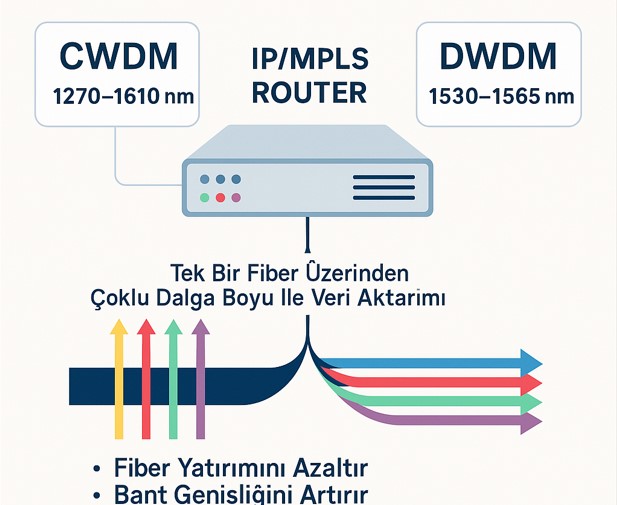
Although CWDM and DWDM technologies are often mentioned together with IP MPLS Routers, these two architectures operate at functionally different layers. Understanding this difference correctly is critical for designing a healthy fiber infrastructure.
The Role of IP MPLS Router
IP/MPLS Routers:
-
Route IP packets and MPLS labeled traffic
-
Perform Ethernet-based data transmission
-
Produce optical signals at a single wavelength through optical modules
-
Connect to CWDM/DWDM devices as a signal source
An important point is this:
An IP MPLS Router is not a CWDM or DWDM device.
The Router does not multiplex or separate wavelengths; it only produces an optical signal at a specific wavelength.
The Role of CWDM / DWDM Devices (MUX / DEMUX)
CWDM and DWDM devices, on the other hand:
-
Combine optical signals arriving at different wavelengths onto a single fiber (MUX)
-
Separate multiple wavelengths arriving on a single fiber (DEMUX) and route them to the relevant devices
-
Operate at the physical layer (Layer-1)
-
Are typically passive optical devices (do not require power if there are no amplifiers)
For this reason, CWDM/DWDM devices:
-
Do not process data content
-
Do not distinguish between IP, MPLS, or Ethernet
-
Only manage light
Wavelength and Channel Logic in CWDM and DWDM
CWDM Channel Structure
In CWDM systems:
-
Wavelengths are typically in the 1270–1610 nm range
-
Channel spacing is approximately 20 nm
-
Maximum of 18 channels are available
-
Cost is low
-
Preferred for short and medium distances
CWDM is ideal for projects where the number of fibers is limited but ultra-high capacity is not required.
DWDM Channel Structure
In DWDM systems:
-
Wavelengths are typically in the C-Band (1530–1565 nm) range
-
Channel spacing can be 0.8 nm, 0.4 nm, or flex-grid
-
40, 80, 96, 160 channels and more are possible
-
Speeds of 10G / 100G / 400G / 800G per channel are supported
-
EDFA and Raman amplifiers provide very long distances
DWDM is the standard solution for operator backbone, power transmission, railway communications, and international networks.
What Does CWDM / DWDM "Support" Mean on Routers?
When an IP MPLS Router supports CWDM or DWDM, it means:
-
The SFP / SFP+ / QSFP / QSFP28 ports on the Router can
recognize CWDM or DWDM-compatible optical modules -
Optical power, temperature, and signal parameters can be monitored
-
Can connect directly to the CWDM/DWDM infrastructure
However:
-
The Router does not perform multiplexing (MUX) or separation (DEMUX)
-
Each port means a single wavelength
Multiple wavelength management is always handled by external CWDM/DWDM devices.
CWDM / DWDM MUX-DEMUX Operating Principle
The basic operating logic of CWDM/DWDM devices consists of two main functions:
Multiplexing (MUX)
-
Signals coming from Routers, each at a different wavelength
-
Are combined onto a single fiber line
Demultiplexing (DEMUX)
-
Multiple wavelengths arriving on a single fiber
-
Are separated again and routed to the relevant Router or Switch ports
Through this structure:
-
Dozens to hundreds of connections can be carried over a single fiber
-
Fiber infrastructure is used at maximum efficiency
Point-to-Point (P2P) and Point-to-Multipoint (P2MP) Architectures
Standard CWDM / DWDM Structure (P2P)
By default, CWDM and DWDM systems:
-
Operate in Point-to-Point (P2P) mode
-
Have a single common fiber port
-
Connect to a single CWDM/DWDM device on the far end
For this reason, they are not directly suitable for P2MP architecture.
How is P2MP Architecture Provided with DWDM?
In DWDM systems, P2MP requirements are met through the following methods:
OADM (Optical Add-Drop Multiplexer)
-
Specific wavelengths can be dropped at intermediate points
-
It is a passive solution
-
Channel count is limited
ROADM (Reconfigurable OADM)
-
It is an active and flexible DWDM solution
-
Channel-level routing can be performed
-
Common in operator backbones
-
Highly costly
Capacity Increase with IP MPLS Router + DWDM
On an IP MPLS Router, you may have:
-
2 × 100 Gbps
-
4 × 100 Gbps
-
or 400G / 800G ports
available.
Each of these ports:
-
Using different DWDM wavelengths
-
Can be transmitted over the same fiber
Total capacity is managed with:
-
Router-level IP/MPLS Load Balancing
-
MPLS Traffic Engineering
-
Segment Routing (SR-MPLS / SRv6)
.
This approach:
-
Does not require fiber investment
-
Increases capacity without interruption
-
Is the standard practice of operators
Optical Power and Attenuator Use at Long Distances
Long-distance DWDM modules:
-
Typically operate in the 1550 nm band
-
Have high Tx (optical output) power
DWDM MUX input ports, on the other hand:
-
Support a specific power range
For this reason, when a high-power module is used at short distances:
-
Power is reduced using an optical attenuator
-
Damage to DWDM equipment is prevented
This method:
-
Is standard practice in telecommunications and ISP infrastructures
Future-Oriented IP MPLS + DWDM Architectural Approach
Today's most appropriate design approach is:
-
DWDM infrastructure is built based on maximum future capacity
-
Routers are connected according to initial requirements
-
As capacity increases:
-
New 100G / 400G / 800G ports are added to Routers
-
New channels are activated on the DWDM side
-
-
Traffic over IP/MPLS is managed dynamically
This architecture:
-
Provides long-term investment protection
-
Offers operator-level scalability
-
Is ideal for energy, railway, and telecommunications projects